
I’m going dive into the theory of laser alignment, show the math and the jigs I built to put that math into practice. This post is for someone who wants the “why” behind a lot of the online material on laser cutters. If you just want some practical tips on how to better align your laser, skip to the end. I won’t compete with the excellent videos that show the practical side of alignment.
So let’s dive in . . .
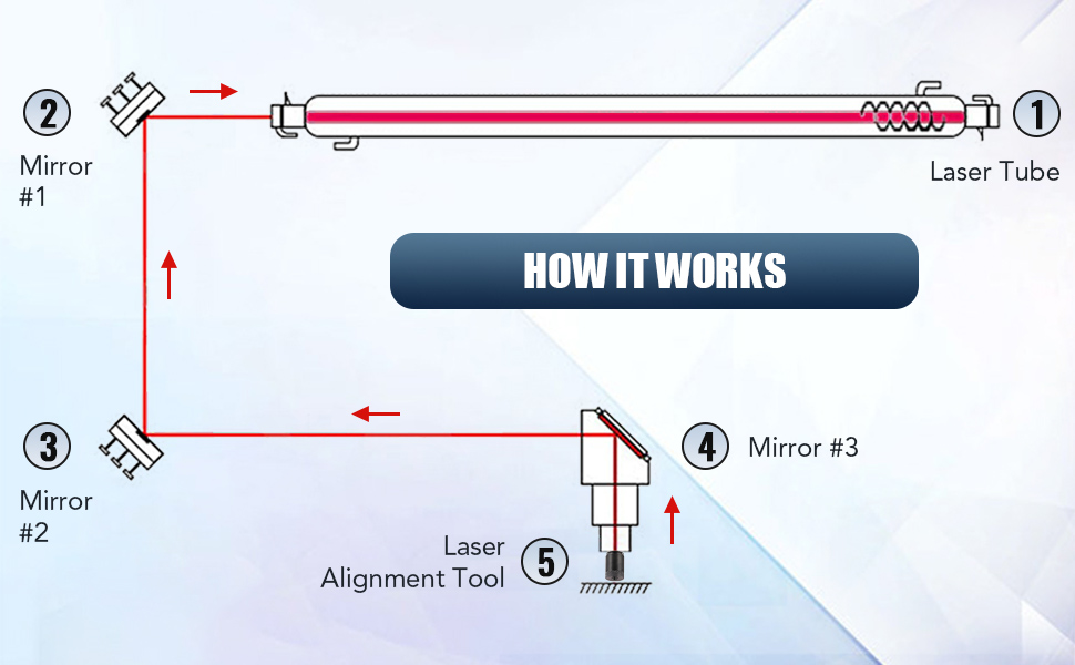
My laser cutter is CO2 based, optimized for precision material processing. The laser tube generates a coherent beam at 10640 nm, which is directed via a series of mirrors (1, 2, 3) before focusing on the workpiece. Each mirror introduces minimal power loss, typically less than 1% per reflection, depending on the coating and substrate quality. The beam’s path is engineered to maintain maximal intensity, ensuring that the photon density upon the material’s surface is sufficient to induce rapid localized heating, vaporization, or ablation.
The choice of 10640 nm wavelength for CO2 lasers is driven by a balance of efficiency, material interaction, and safety. This far-infrared wavelength is strongly absorbed by many materials, making it effective for cutting and engraving a wide variety. It provides a good balance between power efficiency and beam quality. Additionally, this wavelength is safer to use as it’s less likely to cause eye damage than shorter, visible wavelengths (often 400-600 nm). Fiber lasers also have a shorter wavelength (around 1060 nm) which is more readily absorbed by metals.
However, 10640 nm has drawbacks. Its longer wavelength limits the ability to finely focus the beam compared to shorter wavelengths, affecting the achievable precision. The diffraction limit provides the smallest possible spot size \( d \) given by the formula \( d = 1.22 \times \lambda \times \frac{f}{D} \), where \( \lambda \) is the wavelength, \( f \) is the focal length of the lens, and \( D \) is the diameter of the lens. The bigger wavelength needs a bigger lens or a smaller focal length to make a small hole. Since the machine size is limited, the longer wavelength results in a larger minimum spot size. This larger spot size limits the precision and minimum feature size the laser can effectively cut or engrave.
You can’t adjust the 10640 nm wavelength, which is a consequence of the molecular energy transitions in the CO2 gas mixture. This specific wavelength emerges from the vibrational transitions within the CO2 molecules when they are energized. The nature of these molecular transitions dictates the emission wavelength, making 10640 nm optimal for the efficiency and output of CO2 lasers.
The Omtech 80W CO2 Laser Engraver is fairly precise with an engraving precision of 0.01 mm and a laser precision of up to 1000 dpi. This is made possible due to its robust (ie, big heavy machine) construction and the integration of industrial-grade processors that handle complex details and large files efficiently. The machine operates with a stepper motor system for the X and Y axes, facilitating efficient power transmission and precise movement along the guide rails, ensuring a long service life and high repeatability of the engraving or cutting patterns. This level of motor precision enables the machine to handle intricate designs and detailed work, crucial for professional-grade applications.
But! Only if the laser beam is well calibrated. Let’s look at the math of that.
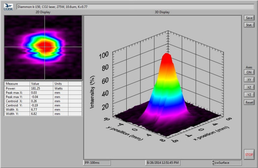
First all intensity values follow the inverse square law, with light, the intensity of a laser beam is inversely proportional to the square of the distance from the source. Mathematically, this relationship is depicted as $$I = \frac{P}{4\pi r^2}$$, where \( I \) represents the intensity, \( P \) the power of the laser, and \( r \) the distance from the laser source. In practical terms, this means that a small deviation in alignment can lead to a significant decrease in the laser’s intensity at the target point.
Visually, laser intensity looks like this, so small drop off in \(r\) leads to big drops in \(I\).
Laser cutters can’t put the whole tube in the cutting head, so they need three mirrors to get to a cutting head that can move in a 2D space.
With this geometry, the effective power at the surface of the material is:
\[ P_{eff} = P_{0} \times T_{m}^{3} \times T_{l} \times T_{f} \]
Where:
- \( P_{0} \) is the initial power of the laser tube.
- \( T_{m} \) is the transmission coefficient of each mirror (a value between 0 and 1).
- \( T_{l} \) is the transmission coefficient of the focusing lens.
- \( T_{f} \) accounts for any additional factors like the focus quality or material properties.
In my case \( P_{0} \) would be 80 watts. I don’t have values for for \(T_l\) and \(T_f\). \(T_l \) typically ranges from 0.9 to 0.99, indicating that 90% to 99% of the laser light is transmitted through the lens. I would love if anyone has these measured parameters for Omtech.
In reality there is alignment error. Precise calibration matters a lot with lasers where a millimeter of misalignment can exponentially diminish the laser’s intensity and focus, impacting its effectiveness. Practically, my Omtech AF2435-80 can’t cut basic sheet goods without lots of tweaking. If \( e \), representing the alignment error at each mirror, would impact the effective path of the laser beam and could lead to a decrease in the energy density at the point of contact with the material. This error would affect the power \( P \) actually hitting the target area \( A \), therefore altering the energy density \( E \) and potentially the depth \( d \) of the cut.
$$ P_{eff} = P_0 \times (T_m – e)^3 \times T_l \times T_f $$
To actually cut something you need to remove the material, which takes power and time. A laser doesn’t burn material away like a hot light saber. Laser ablation is a process where the intense energy of a focused laser beam is absorbed by a material, causing its rapid heating and subsequent vaporization. This localized heating occurs at the laser’s focal point, where the energy density is highest. It can be so intense that it instantly removes (ablates) the material in the form of gas or plasma. The efficiency and nature of the ablation depend on the laser’s wavelength and the material’s properties. Essentially, the laser beam’s energy disrupts the material’s molecular bonds, leading to vaporization without significant heat transfer to surrounding areas, enabling precise cutting or engraving.
I like cutting wood. Here, the laser’s focused energy causes the wood to rapidly heat up at the point of contact. This intense heat can char or burn the wood, leading to a change in color and texture. In essence, the laser beam causes pyrolysis, where the wood decomposes under high heat in the absence of oxygen. This process can create smoke and a burnt appearance, but it’s controlled and doesn’t ignite a fire like an open flame would.
To cause ablation, the energy applied to a material is a function of power, spot size, and interaction time, affected by alignment errors \(\bar e\). The energy density \( E \) is defined by the laser power \( P \) divided by the spot area \( A \), and is given in watts per square meter. The interaction time \( t \), which is the time the laser is in contact with a point on the material, is crucial for determining the amount of energy absorbed. This is especially important because it affects the cutting depth \( d \) and is defined by the inverse of the feed rate \( v \). The burning power, or the energy delivered to the material, can be calculated by:
$$ E_{burn} = \frac{P_{eff} \cdot t}{A} $$
Substituting the effective power above, gives us the energy at the surface.
$$ E_{burn} = \frac{P_{eff} \cdot t}{A} = \frac{P_{eff}}{v \cdot A} $$
Since \( t \) is inversely proportional to \( v \) (the feed rate), and the depth of the cut \( d \) is proportional to the energy density over time, the equation can be further refined to calculate \( d \):
$$ d \propto \frac{P_{eff}}{v \cdot A} $$
This equation shows that the cutting depth \( d \) is directly proportional to the effective power \( P_{eff} \) and inversely proportional to the product of the feed rate \( v \) and the area of the spot size \( A \).
So, if you want to cut effectively, you maximize your power, hit at the right speed and get your beam as focused (small) as possible. To do this practically, you want to make sure you are cutting at the right focal distance and with the right alignment. You also want clean mirrors. The focal distance is determined by a ramp test. I’ll cover alignment below. Cleaning the mirrors increases the \(T_I\).
Alignment
To align my laser, I just couldn’t use the tape. First, you have to align for precision and then get accuracy through moving the tube. To get precision from mirror 1, you have to strike a target close to the source of mirror 1 and then farther away. There are many many videos that walk you through the sequence (mirror 1-2 close, mirror 1-2 far, etc). I want to focus on the math of precision.
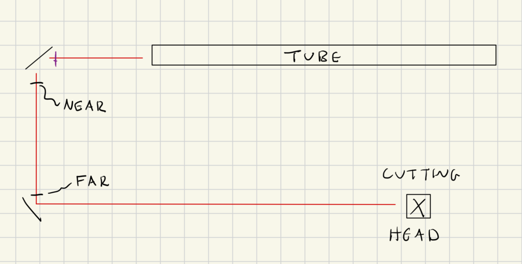
The pulses will look like this:
Now, we can look at the x-dimension to see what point a straight line would intersect, call this \(x\).
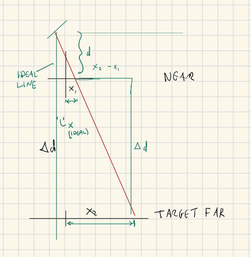
Writing out the similar triangles gives:
For the x-coordinate:
$$ \frac{x – x_1}{\Delta d} = \frac{x_2 – x_1}{d + \Delta d} $$
For the y-coordinate:
$$ \frac{y – y_1}{\Delta d} = \frac{y_2 – y_1}{d + \Delta d} $$
So we can solve for the point a straight line would make when two targets are space \( \Delta d \) apart where \( \Delta d = d_{far} – d_{near} \):
- For the x-coordinate:
$$ x = x_1 + (x_2 – x_1) \cdot \frac{d_{near}}{d_{far} – d_{near}} $$
- For the y-coordinate:
$$ y = y_1 + (y_2 – y_1) \cdot \frac{d_{near}}{d_{far} – d_{near}} $$
Where:
- \( x \) and \( y \) are the coordinates of the true point where the laser needs to be positioned.
- \(x_1, y_1\) are the coordinates where the laser hits when the target is near.
- \(x_2, y_2\) are the coordinates where the laser hits when the target is far.
- \( d_{near} \) is the distance from the laser to the target when it is near.
- \( d_{far} \) is the distance from the laser to the target when it is far.
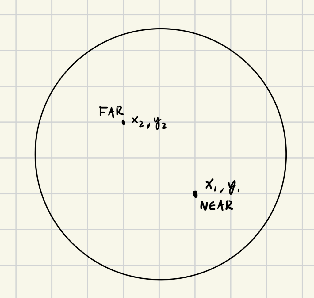
Plotting what this looks like shows the relationship between the true dot and the near and far dots. It’s on the other side Here are the dots where near is blue, far is black and the red dot is the true dot that represents the laser moving in a straight line. These are extreme cases that would represent a pretty misaligned tool.
If I run a simulation with d = 5 cm and \(\Delta d\) = 30 cm with a max distance from the center of 10 mm, I get:
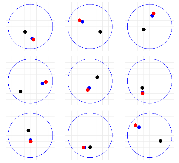
So this is odd: the red dot isn’t in between the black and blue dots. The line connecting those two dots is the path of the laser at its current orientation. I really want to think that the ideal spot would be in between these two dots. However, the intuition that the point (x, y) might average out and fall between (x1, y1) and (x2, y2) is based on a misunderstanding of how the alignment of a laser system works. In a laser alignment system, when you’re adjusting the laser to hit a specific point on a target at different distances, you’re effectively changing the angle of the beam’s trajectory.
The laser source does not move directly between (x1, y1) and (x2, y2), but rather pivots around a point that aligns the beam with the target points. Since the laser’s position is being adjusted to correct for the angle, not for the position between two points, the corrected point will lie on a line that is extrapolated backwards from (x1, y1) and (x2, y2) towards the laser source.
The resulting position (x, y) where the laser needs to be for the beam to be straight and hit the same point on the target at any distance will be on the extension of this line and not necessarily between the two points (x1, y1) and (x2, y2). This is due to the nature of angular adjustment rather than linear movement. The position (x, y) is essentially where the angles of incidence and reflection converge to keep the beam’s path consistent over varying distances. It’s pretty cool that two points give you this angle. In fact, the ideal point is located further back on the line of the laser beam’s path extended backward from the near and far positions, which geometrically cannot lie between the near and far positions on the target unless all three are equal. Fortunately, as the points get very close, you can just fudge around with the dials to get these on top of each other which is probably what most people do.
If the plots are closer to the center, it’s much easier to just not worry about the math. If I constrain the points to be 2 mm from the center:
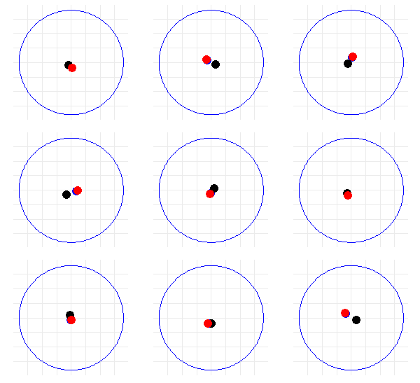
Too complicated? Here are some basic rules from the math:
Just aim for where the nearest point hit at the farthest distance away. (The near point has less error.)
- Linear Alignment: The points are always in a straight line. This is because the red point is calculated based on the positions of the blue and black points. It represents the position where the laser should be to maintain its alignment with the target at both distances. The calculation creates a direct linear relationship between these three points.
- Relative Distances: The farther apart the blue and black points are, the farther the red point will be from both of them. This is because a greater distance between the near and far points means a larger angular adjustment is required for the laser, which results in a more significant shift in the red point’s position to maintain alignment.
- Ordering of Points: If the blue and black points are flipped (i.e., if the far point becomes nearer to the center than the near point), the red point will also shift its position accordingly. The ordering of the blue and black points relative to the circle’s center will determine which side of these points the red point will fall on.
- Proximity to the Center: When both blue and black points are close to the center, the red point will also be relatively closer to the center. This is because minor adjustments are needed when the target moves a shorter distance.
- Symmetry in Movement: If the blue and black points are symmetrically positioned around the center (but at different distances), the red point will also tend to be symmetrically positioned with respect to these points along the line they form.
What I did
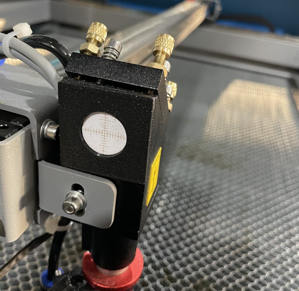
Armed with the right theory, I had to move past shooting at tape, so I used this svg from Ed Nisley to create these targets and I 3d printed a holder for them. This is the jig that fits over the nozzle:
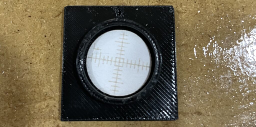
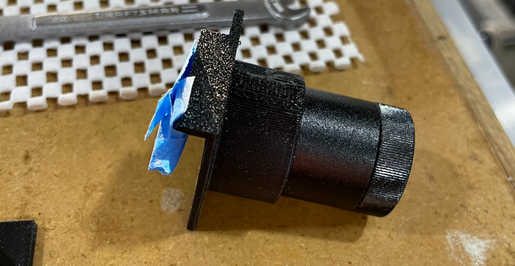
And the jig that fits in the 18mm holes.
I also made a holder for my reverse laser so I could use this in the forward direction:
Armed with all this, I built a calculator and you can poke at my R code.
Also, let me know if you want the STL or svg files for the alignment jigs.
Leave a Reply