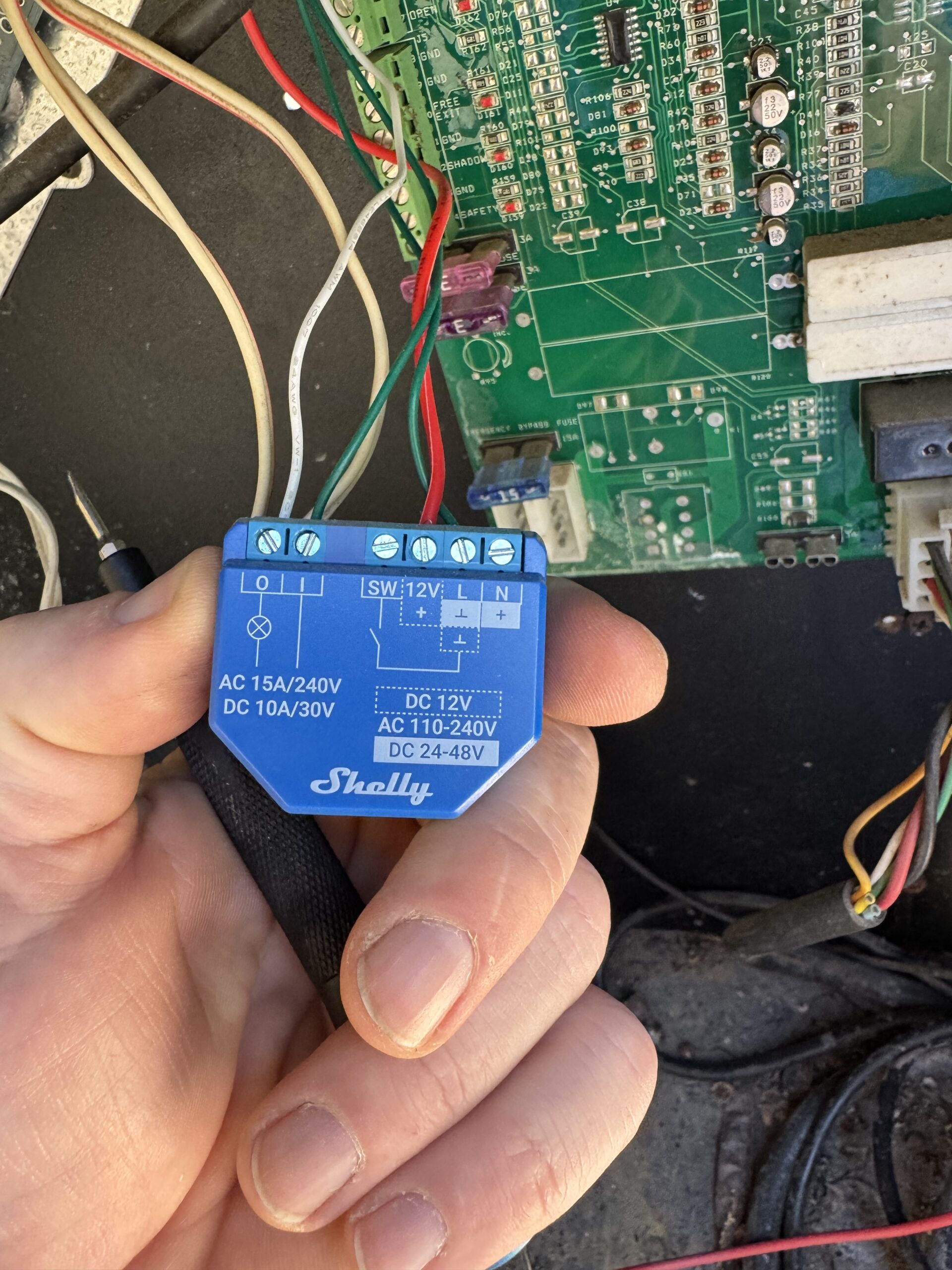
Shapeoko Troubles

I recently encountered an issue when generating a grid of holes for workbench. I had recently planed down an old workbench from our house in New Jersey. I was planning on 20 mm holes spaced in a grid with 96mm spacing to match the festool MFT table. I’m hoping to use the available array of cool attachments and eventually add the aluminum profile to the side. For example, an MFT table can be used as a bench with a variety of different attachments, such as clamping elements and stops.

Unfortunately, the holes didn’t create a proper grid and the spacing was off. I used a CNC machine to cut the holes, but I noticed that they were off. Just looking at it showed that each row had fairly consistent spacing, but the start of the rows varied in the X direction.

To accomplish a 96 mm grid, the g-code was programmed to start at the bottom of the workpiece and move across in a row. This process was then supposed to be repeated until the entire grid was cut. However, as I mentioned earlier, I encountered some issues with the spacing of the holes and had to troubleshoot the problem.

One theory I became aware of online (thanks gdon_2003, Julien, LiamN, SLCJedi and WillAdams) is that set screws are a part of Shapeoko drive system and a loose set screw can cause this type of behavior. That’s because the set screws transfer motion from the motor shafts to the pulleys, which rotate against the belts. They are intended to be pushed tightly against the flat spot on the motor shaft, causing the pulley to turn with the motor. If the set screw becomes loose, the pulley may turn independently of the motor before snapping into place, which can cause issues with the motion of the machine. This may show up as flat spots on circles or other imperfections in projects. You can see why a loose set screw is bad as captured in the screenshot below from this youtube video by See-N-C.

Screenshot that describes how set screws work

Doing some Math

In order to do some analysis on what happened, I needed to register the image and get the location of the points.

The drawpoint command in MATLAB is a function that allows you to draw a single point on an image or plot. You can specify the coordinates of the point on an image using the mouse to record position. Using drawpoint, I recorded the coordinates of the center point of each circle and put this information in a struct. I then wrote code to turn the struct into two arrays: one for the x coordinates and one for the y coordinates. This allowed me to easily analyze the variance in the x coordinates for each column and the variance in the y coordinates for each row.

I was also able to use the drawpoint command in MATLAB to mark points on the ruler captured in the image. This allowed me to easily record the coordinates of the points and then do the math and convert the distances between the points from pixels to millimeters.

I used the pdist2 function in Matlab to calculate the Euclidean distances between my two sampled points and then converted the distances to the desired units through a conversion factor of 610 mm/523.4087 px.

Since the job started at the upper right and progressed down and across, we could look at the variance throughout the job. The variance in the x direction seemed to increase in the last four columns:

x1.2610.36030.58540.76563.24253.963
Variance of X in each Column (in mm)

The variance in the y direction was much bigger across the rows and also increased as the job progressed. I used this MATLAB to generate this: makemm(var(y(:,:),0,2))

y24.753724.573630.623235.246736.3425
Variance of Y in each row (in mm)

To generate the ideal points based on a 96 mm grid, I wrote a function that takes in two inputs, iX and iY, which represent the starting x and y coordinates, respectively. The function first initializes two matrices, X and Y, to store the calculated x and y coordinates for each point. Then, it defines a conversion factor, cf, which is used to convert the units from millimeters to pixels.

Next, the function uses a nested for loop to iterate through each column and row of the matrices. For each iteration, the function calculates the x and y coordinates of the current point by adding the starting coordinates (iX and iY) to the appropriate offsets, which are determined by the loop variables and the conversion factor. The calculated x and y coordinates are then stored in the corresponding elements of the X and Y matrices.

To calculate the root mean squared (RMS) error, I subtracted the actual coordinates from the ideal coordinates to find the error in both the x and y directions and then took the square root of the mean of the squared errors in both directions.

123456
103.64134.867812.579612.847612.0532
21.29864.71474.923613.636513.884112.3934
31.6041.47845.26213.272213.526513.8716
42.61142.536214.100214.219514.898816.2787
56.15646.040717.367317.355818.812919.6045
RMS errors for each hole

You can see the error increasing as the job progresses, but the major error starts in column 4-6, supported by a big jump in column 3, row 4, which supports the idea that the screw isn’t seating well resulting in slippage.

Overall, doing this math allowed me to see what was really going on. By adjusting for the variance at 4,3:

Pattern in Holes

Lauren’s Desk

Lauren was using her desk for art and computing. She sketched out a design and I quickly drew it in sketchup.

Desk Concept

We decided to use an existing top from Home Depot. I probably won’t do this again. The quality is really poor. I had a to gouge out lots of loose wood and we used lots of Cyanoacrylate (“CA”) glue and epoxy to fill in the voids and then used my Lie-Nielsen No. 60-1/2 Adjustable Mouth Block Plane to shave off the excess adhesive. The end result was a nice smooth table, but the wood quality was really poor.

Pocket Hole Calculations

I measured my Kreg pocket hole drill bit as 133 mm long and 9.5mm wide with a pilot hole that is 4 mm in diameter and 12mm long (please comment below if you know the factory dimensions). Getting the Kreg dimensions right is an interesting problem. You can some discussion and calculations at this link and folks have talked about this.

Kreg pocket hole calculations

Since I’ll be screwing pocket holes into the legs, I selected 1″ Long Square-Drive Flat Head Screws for Wood, Black-Oxide Steel, Number 8 Screw Size. I will be using glue as well. The key dimension is the 15 degree angle and the key parameter is the distance between the 75 degree offset plane (green above) and the start of the pilot hole. In this case, I needed zero.

To get this working in fusion 360, I wrote this script.

I then drew the desk in Fusion 360.

desk rendered
Desk Rendered

And used cutlistoptimizer.com to generate the layout.

Cutlist Optimizer

I generated engineering drawings for the desk drawer.

drawer

And also generated drawings for all the components.

Major Desk Components

I’ve been generally unhappy with most table leg brackets, so I designed my own. This was pretty complicated, since they were an odd size that I had to cut out of a solid block of ash.

Brackets

I made them to fit the dimensions of the table exactly and use a lag screw to anchor the legs.

bracket dimensions

To build these brackets, I laser cut a jig to ensure I cut the holes at the right places. This worked out really well using my crosscut sled and drill press.

Jig Design

The final desk came together pretty much exactly according to plan.

Final Product

Torsion Table for Shapeoko

I needed a torsion table to make sure my Shapeoko XXL had a solid foundation. Dimensions for the Shapeoko are available here. The basic idea of a torsion table is to use two thin layers of material on either side of a lightweight core, usually a grid of beams. Torsion boxes are used in wings and vertical stabilizers. The final product can resist torsion under an applied load. The torsion box uses the properties of its thin surfaces to carry the imposed loads primarily through tension while the close proximity of the enclosed core material compensates for the tendency of the opposite side to buckle under compression.

I found some great data in the links below:

  • great collection of ideas here
  • and more ideas here
  • This post was great at getting ideas.

Marc Spagnuolo, a.k.a. “The Wood Whisperer,” put together a pretty comprehensive 20-minute-plus video on how he built his. Spagnuolo shows you how to get past the dilemma of building your first torsion box, which is: how do you construct a perfectly flat surface, before you’ve got a perfectly flat surface to assemble it on?

My design was intended to look similar to this, but I didn’t like the idea of making sure all the individual pieces were straight, so I build a design based on half-lap joints.

Example Build

Lining everything up perfectly was super easy after cutting the slots. MDF is an amazing material.

Half Lap Assembly

The end result was intended to look like this by using the Hopkins Mfg Corp Workbench Kit 90158MI.

Shapeoko Table

My end design looked like this (I always use mm for dimensions).

I used my table saw to cut down the core pieces all to the same height. A torsion box is a completely flat, very sturdy and relatively lightweight surface, and anyone designing anything structural and rectilinear should understand its principles. The concept is simple, even if construction can be tedious: Two flat, horizontal surfaces are sandwiched over a grid of crossmembers, and once the sandwich is glued shut, a rigidity much greater than that possessed by the individual parts is achieved.

Pieces Cut

I added shims to the bottom of the saw horses to make sure the base was level. I used lots of glue.

Assembly drying

By using half-lap cuts I was able to get all the spacing right. It was critical to square the boards.

Half-laps cut

Here you can see my use of pocket screws and my testing of the table to ensure it is level.

Inital design

I love using cutlist optimizer to speed up my cuts and optimize the use of the wood. I’ve designed cutting algorithms myself in the past and this online tool is fast, accurate and excellent. (https://www.cutlistoptimizer.com/). I did make a design change by ripping long strips so I could avoid the inaccuracy of all the small cuts.

Cutlist

I made a video of my design process. I made a component with half-laps cut out, replicated it with design tools, flipped a copy that I rotated 90 degrees.

Video of the Design Process

Kerf Mounted Corner Brackets

Kerf Mount Corner Brackets are great. But it takes some thinking if you are working with larger lumber. I recently purchased these and these from amazon.

The corner bracket looks like this:

The trick is figuring out where to cut the leg at 45 degrees and the kerfs, especially if the leg isn’t square. I was going to work out the geometry of this, but instead I measured the bracket, drew a horizontal profile in visio and then measured the geometry. Since the leg isn’t square, I had to decide where the bracket mounts flush. I included my drawing here in the hopes that it may be helpful to you.

There are instructions here.

Lauren’s Bed

Overall Design

Lauren was disappointed when we had to take 30" away from her already small room to build a bench for a duct after adding a furnace to the third floor.

Lauren did an initial sketch of what she wanted to build. Her overall goal was to maximize the space available in a smaller room. This meant we needed lots of storage and that we wanted to use the surface area of the bed.

lauren's bed

We looked around for some design ideas. We decided to match the trim color of the room and use the bottom for storage.

design ideas

I drew this up in Sketchup and decided on a design that used pine 2×4 and 2×6 to make the frame, with poplar sides. By using an internal frame and a several stage layup, we could make lots of adjustments.

We decided on three drawers on the bottom using full extension hardware ball bearing side mount drawer slides. I found these on Amazon, which have been excellent quality. For my shop shelves, I purchased two Everbuilt drawer slides at Home Depot for 3x the cost that were inferior in quality.

bed layout

All this would be supported by an internal frame that would allow us to adjust to all the non-level components of the room.

frame

I like notching the pine board with my 5-1/2" Craftsman C3 19.2v Circular Saw. While an old tool, it is super light and I can use my speed square as a guide to notch out the pine quickly. I tried using my table saw with a crosscut sled, but the handheld saw was a lot easier.


drawers

For all joinery we used pocket screws and also #10 biscuts.

We laid out the frame on the floor and ensure the top frame was level, but we also should have leveled the bottom. Not leveling this created a lot of issues when we had to put in the drawers and build the outside frames.

The frame for the inside was built using lots of lap joints, held together by wood glue and pocket screws.

interior frame

I don’t build my own face frames. It’s awesome to order them professionally finished. I ordered them from the cabinet door store, which I can’t recommend enough.

Shaker Cabinet Door
Wood Species:Paint Grade Maple w/ HDF Panel
Frame Width:2 1/4"
Finish ($11.97):Simply White OC-117
Door Width (in):18.75
Door Height (in):10.75
Total Area (sq. ft.):1.3997395833333

or $44.23 a face.

One big mistake of my design was failing to account for non-straight boards and my over-optimism in everything lining up. Since the purple boards below were rigid, any mismatched angle would effect two drawers. This trapped me in the middle of a highly coupled problem where adjusting one drawer would cause problems with the others. I solved this by cutting 1 inch out of the middle of each purple board so I could adjust each one independently. Lesson learned: designs should always account for reality and provide the ability to adjust.

drawer slides

In order to get the drawers to sit at the right height, I cut out spacers for each of the drawers before installing the sliding tracks.

Result

The end result was awesome. Lauren loves her bed and we learned a lot putting it together.

Sled for Picture frame

Making perfect miters is hard and doing the math to get the inner rabbit dimension to add up isn’t easy.

One thing I’ve learned about making stuff is that jigs make life better.

I love making picture frames. Not only do I enjoy saving money, but I love dressing up art. Even a bad piece comes alive in the right frame. The problem is that making perfect miter cuts is hard. I started making frame on my miter saw, but that required a lot of tweaking and adjustment between the cuts.

There are great references online to use sleds to make picture frames. I like this one and the original but I don’t like the idea of a lot of the sled’s weight hanging off the front of the table. I also wanted to leverage the fairly accurate right angle of an aluminum framing square. As long as the blade is straight, the angle will add up to 90 deg, even if my sled is off by a fraction of a degree.

This was designed with two key constraints:

  • The two corner pieces must add up to 90°
  • each matching side must be the exact same length

This sled covers both of those issues as well as it allows for larger picture frames than a traditional miter sled stop system. Picture frames are not measured by the inside or outside length but by the rabbit so if your artwork or matte is 5×7 we can set the stop to create a frame for that exact size.

To make sure there is no play in the runners for the sled, I used the MicroJig Zero Play Guide bar system that adjusts to fit any table saw.

We have the dewalt dwe7491rs and I’m saving a a link to the manual here.

Some links that helped me:

In my table saw, the miter slots are 3/4 (wide) x 3/8 (deep). Distance from the right edge of the left trench to the left side of the blade is 5 15/16". From left side of the right trench to the right side of the blade is 6 1/8". Using Diablo 60 tooth blade.

Wiring for 3HP 220V (for Laguna Tools 18|Bx)

I recently purchased a Laguna Tools 18|Bx 3HP 220V 18″ Bandsaw, specifically a MBAND18BX2203, and needed to wire a 220 Volt outlet. I’ve done a fair bit of electrical work (both low and high voltage), but I had a couple questions.

Just for the record, I enjoyed this video to make sure everything was setup correctly and this unboxing video was helpful. Also, here is the manual. The instructions weren’t great, but the wiring digram in the manual was helpful. YouTube and web forums are incredible for learning how to do new things like this. This article, Understanding 240V AC Power for Heavy-Duty Power Tools, was super helpful.

The 18BX2203 has a 12-amp 3 HP 220 volt 1 phase Leeson motor, with a 20 Amp recommended breaker. (Engines use more current on startup. Why not more Voltage?). 220V is a somewhat outdated nomenclature for the US system, but tools like this have adequate tolerance to take 240 without problems.

Laguna made this confusing since their website for the 18BX, differed from the manual. The website recommended a 20 amp breaker, while the manual recommend 15.

mismatch

The machine’s wiring diagram showed me a couple important things. First, I have no need for a neutral wire and the saw has a NEMA 6-15 plug.

wiring

The single phase motor will need at least 12-amps of continuous current at 240V (hot 120V + hot 120V) plus a ground. Here in the US, we have 240V single-phase residential, with a center tap. The center tap is called neutral. This is called “Split-phase” since you can grab the outer “phase” wires (hot-hot) or grab one phase and neutral for half the voltage.

This diagram cleared everything up for me:

Where I found myself confused was on the “single-phase”, if a “normal” outlet grabs one phase, and a neutral for half the voltage, wouldn’t a 240V setup have two phases? There actually is a 2-phase, but it’s weird as heck. It was basically two single-phase circuits set 90 degrees apart, and requires 4 wires instead of 3 but only carries about 14% more power for 33% more wires. Needless to say it wasn’t popular.

This diagram cleared it up for me. The amplitude of 120V on each leg adds to 240V at the same frequency. The current doesn’t add since the flow remains the same. A 240V-only piece of gear connects to two hot legs and a ground (no neutral), so if it pulls 20A, that 20A has to be going in one hot leg and out the other hot leg — there’s nowhere else for it to go! (In other words, it draws 20A, period — the legs do not “add together”.)

In setting up a 20-amp circuit, I had to make sure this worked with my setup. Per the table in the manual, I need at least 14 guage wire, so I went with 12 guage which I needed for the 20-amp breaker anyway.

wire thickness

How many wires?

I initially was going to use 12/2 wire, but I decided on schedule 40 conduit with Thermoplastic High Heat-resistant Nylon-coated THHN wire. I like this reference on wires.

I initially thought I would need to have 4 wires (a 12/3 wire), both a neutral and a ground in addition to two hot wires. After thinking about it a little bit, it made sense two use three wires total, since I was setting up a dedicated circuit and the ground and the neutral will have the same purpose. (The neutral is connected to the ground in the panel.)

What receptacle do I use?

The bandsaw came pre-wired with a 220V NEMA 6-15 3-pin plug. I used this page to make sure I used the correct outlet. One of the decisions I had to make was if I wanted to use a twist lock plug, but I didn’t consider the benefit worth the extra work to re-wire the saw.

For this setup, I needed a NEMA 6-20.

By the way, I learned that due to an exception in NEC, I’m allowed to plug 15A-plugged loads into either a 15A or 20A circuit. Further, a 20A circuit is allowed to have 15A sockets on it (as long as there are 2 or more sockets, e.g. the above NEMA 6-15 will suffice).

I decided on 20 Amp Commercial Grade Double-Pole Single Outlet, White which has two connections for hot and one ground wire and is a NEMA 6-20R, 2P, 3W.

Breaker

This is the most simple part. I need two 20 amp breakers that connect to different leads to get both parts of the split phase. This one will work.

A mudroom

Our remodeled home included a mudroom and I was tasked to build the fancy hall trees that would store all our kids shoes, jackets and stuff. I am a member of the Wood Whisperer Guild and loved their design and construction techniques.

Design

I was inspired by designs like this.

Designing and building things parametrically in AutoDesk Fusion 360 has been a game changer for me, but this one was tricky since I wanted the start and end of the hall tree to include the width of the ply.

In order to make the width between the front facing the same, I had to do some math because the first and last boards were flush to the ends. The first and last cubby interior width is a and the middle widths is b. This is where a little math made the design a lot more clear and where the real cabinetry pros get confused. Hey! I’m an engineer not a carpenter without years of experience to just do this stuff.

$$ a = \frac{1}{4} (l – 6\, w) \; \text{and} \; b = \frac{1}{4} (l – 4 \,w) \; \text{and} \; k = \frac{l}{4} – \frac{3}{2}\,p$$

Or more generally:

$$b = \frac{l}{n} – w \; \text{and} \; a = \frac{l}{n} – \frac{3\,w}{2}$$

where n is the number of bins. We explored 4, 5, 6 to figure out what best used the space.

First, I needed to design five cubbies with equal width. I love building things, but use stock pieces and don’t have the time to glue up countertops or make faceframes. Because of this, I built this on top of an Ikea Karlby countertop (Article no: 703.352.12) which is super straight, low cost and beautiful. I played with the design to optimze the cutouts from 4×8 sheet of three quarter inch plywood. As an aside, I get my grade A or B plywood from Huston Lumber. The Home Depot stuff has a thin veneer and risks delaminating and is a lower version of grade C.

The final design resulted from lots of discussions in the space.

And used the following parameters. Calculating parameters made the design a lot easier to build.

Parameter Unit Value
room_length m 3.068 m
room_height m 2.5 m – 9 cm
ply mm 19 mm
countertop_height mm 37 mm
countertop_depth mm 650 mm
cabinet_width mm 575 mm
cubbies_length mm room_length – cabinet_width
cubby_depth mm 400 mm
base_cubby_depth mm 0.9 * countertop_depth
dado mm 6 mm
facing_width mm 1.5 in
facing_ply mm ply
a mm ( cubbies_length / n ) – ( 3 * facing_width ) / 2
b mm cubbies_length / n – facing_width
k mm ( 1 / n ) * ( cubbies_length – n * ply )
base_cubby_height m 18 in – countertop_height
top_cubby_height mm room_height – countertop_height – base_cubby_height
shelf_width mm k + dado * 2
cubby_height mm 1300 mm
len mm cubbies_length / n
n 5

I used the parametric features pretty extensively, basing everything off of fractions of the the total shelf length and room height.

The heart of fusion 360 is the sketch. By fixing the sketch and understanding the timeline, its possible to break down the design into a set of modular components that help you keep complex designs under control.

From there, I was able to use mapboards pro to get a cutlist, which I uploaded to cutlist optimizer to produce a fairly optimized design that efficently used three sheets.

Overall, fusion 360 estimates the total weight as 172 Kg, which is probably accurate with the long walnut countertop. I was planning on doing a stress analysis on the design, but I’m saving that for a future project.

Manufacture

After understanding my design, I primed everything with BIN primer that sprays on easily using my HVLP Harbor Freight gun. I use Harbor Freight guns for BIN because the cleanup is easy and I can frequently replace the gun. Since I sand the primer, the finish matters a lot less. For finish work, I use my FujiSpray MiniMite.

After priming, I used my Festool TS55 track saw to cut down the sheets. To make everything accurate, I made two jigs using 1/4 inch thick plywood and Starbond CA Glue. Reading up on ETHYL CYANOACRYLATE is recommended. It’s pretty cool.

This let me back super accurate cuts without needing to move big sheets of plywood on the table saw.

show the reader the cut pieces

After the pieces were cut, I went back to the model to update the dimensions I actually cut, which at my current skill level is around \(1 \pm \text{mm} \). In order to get everything consistent, I use the table saw to cut things down to equal dimensions and ensure everything is square.

Dimension Value (mm) My Value
Shelf Width (a) 482.1 481
Shelf Width (b) 491.6 492
Top Depth 400 399
Base Depth 585 582.5
Vertical Side Height 1952.8 1953
Base Height 420.2 419
Ply 19 18.67

Pocket Holes

drawing of kreg dimensions

I had to figure out how deep to cut the pocket hole with the 6mm dado. After building a drawing, it made sense to set the depth of the jig to \(\frac{5}{8}\).

For myself and others, I saved the chart I use here for depth and screw length selection.

I used stickers to make sure the screws from my pilot holes wouldn’t bump into each other.

I had a great helper to help me drill the pocket holes.


I measured the pocket hole screw to make sure I wouldn’t cut through the other side.

Assembly

I decided on which components I wanted to manufacture. Also during this time, I realized that I’m going to need a back to add strength to the overall design.

Components to manufacture

Finishing

painted bottom

I assembled the top cabinetry inside to make it easier to lift everything up.

mudroom

I love pocket hole joinery, but had to hide the screws on the top of the shelf and used Kreg Plugs. I had to cut down the plugs with a flush trim saw and used bondo putty to fill in. It’s great, you can’t see or feel that a hole was there.

I’ve always loved the finishing process and here I did several layers of sanding and putty. Mostly using two-part bondo and 320 grit sandpaper. I highly recommend the Festool ETS 150 with their dust collector. No dust and a super consistent finish.

After sanding 100 grit, then 180, I used Bondo multipurpose putty for extra strength. I also used clamps, a straight edge and bondo to ensure the edges were square.

The final product came out better than I expected. I still need to order and install the cabinet doors, but the final product is something I’m proud of.

mudroom

Simple 4×8 workbench

In building out my workshop, I was tired of setting up sawhorses the garage and realized that I needed to better use the floor space of my shop. Setting up a 4×8 workbench is a right of passage for the aspiring maker. They are quick to make and super useful.

Most of them are pretty simple:

Some are just epic:

My main goal was to make an outfeed table and a common surface to cut with my festool track saw. I also wanted a cabinet makers vice and a holddown system based on t-tracks or MFT hardware.

I went with t-tracks and these clamps and these tracks. These have been incredible and I use them with nearly every project. Initially, I bought these intersection kits, but found I could use my miter saw with the right blade to cut all the intersections.

I was initially excited about making the top out of Valchromat, but the pain of sourcing that in a covid19 enviornment was too much of a stretch and I settled on Home Depot MDF for the top. To be able to swap out the top, I glued everything but the top which I used about 10 pocket screws to attach.

I was inspired by April Wilkerson to build the workbench completely out of plywood with pocket screw joinery and I’m really glad I did. I needed the workbench to be mobile and incorporated a Workbench Caster kit that retracts to give me the benefit of firmly planting the workbench to the ground. Unlike other designs, I planned for the bottom base of plywood to directly touch the ground, since I didn’t see a benefit to having space underneath the table and I wanted 100% rock solid surface.

Before building the design I came up with the following requirements:

  • Important storage needs were for my spare wood, my growing collection of jigs and saw blades and framing supplies.
  • Storage for:
    • store foam for framing (30X40 acid free mat boards)
    • saw blades and push sticks
    • Festool tracks (The rail is 183mm wide, plus additional 2-3mm plastic lip)
    • My large and small T-squares
    • All my small parts bins
    • Spare wood
  • The surface needed to be covered with t-tracks for easy workpiece clamping or MFT (pattern of holes 20 mm in diameter, and are spaced 96 mm center to center) (I chose t-tracks)

The sole complication of my design was incorporating my table saw that wasn’t meant to be surrounded by plywood. The goal of the design was to save a lot of space and provide me an outfeed table, but getting the top flush and level was challenging. (I had to use my car jack and shims.) The most difficult part was cutting out the voids for the guide rails and the lever for the riving knife. This was really hard because both of them intersected the tabletop so I had to use a router and a chisel to carve space out of the tabletop. I was inspired from others who built similar designs, but I thought I could signifcantly improve on them.

To get me thinking through my design, I did a quick design in Sketchup.

Once it was time to get serious, I used Fusion 360 to build a refined design. Fusion 360 (free for hobby folks) uses parametric modeling which gives me the ability to modify the model as I take measurements. One of the important impacts of parametric design is the ability to keep tweaking the design as I optimize cutting out of the plywood. Also, I can start designing without measurements, and in this case I did most of the design in the car on the way home from the beach.

Once home, I was able to get some key measurements:

Fusion 360 is a serious modeling solution and I added more detail, like the ability for the fence to go to the left of the saw.

For all joinery, I used Kreg pocket screws with 2.5 inch cabinet screws. I tend to like McFeely\’s and square drive, but Home Depot is so much easier, and they store GRK Fasteners with star drive heads that don\’t strip.

One of the best features of Fusion 360 is the Map Boards Pro extension that allows to generate a cut-list and creates all the relevant bodies as a flat-pack.

This gets me a rough feel of all the boards I need to cut, then I like to use cutlist optimizer which is easy because I just upload the cutlist exported from MapBoards pro.

Mistake

The casters were perfect and rated for 880 lbs each, but the bottom screws couldn’t hold the weight and ripped out of the workbench. More engineering was needed!

I designed a flat plate of aluminum (1/4 inch thick) in which I would tap M5 threads (5mm hole) to bolt the casters into. I made six other holes 5.5mm in diameter for longer m5 bolts that would allow me to bolt them on from the back.

I purchased four Aluminum Flat Bar, 1/4″ x 4″, 6061 General-Purpose Plate, T6511 Mill Stock, from Remington Industries and used my Shapeoko CNC to cut the first 4 mm but I finished them off with special drill bits on my drill press so I could ensure highly accurate hole diameters. To cut the aluminum on the CNC, I used Kodiak Cutting Tools KCT166406 1/8 End Mill. I was cutting a 5 mm holes using 10k rpm with a feed rate of 500 mm/min and plunge of 120 mm/min for a boring operation in fusion 360 with a pitch of 0.5 mm.

Working with metal is just awesome, for one it helps me claim I’m an engineer and maker more than a woodworker only.

For reference, I was able to use
this site for hole sizes and this tap and die set.

Mistake #2

In tapping the threads for the M5 bolts, I used the fine pitch tap (0.75 mm pitch) not the 1mm pitch I should have. This was a problem since you can’t easily find fine threaded bolts. Thank you McMaster Carr for saving me out of this one.

Finished Product

Seriously, this was a super fun project that came together exactly as planned. The t-tracks and clamps are my favorite feature, but I love the huge storage for framing supplies. (I love making custom canvases and frames.)

The metal supports for the casters at the bottom worked out really well.

I need a clamp

So I need a clamp, specifically a corner clamp jig.

Google finds this:

And I was inspired by this fireball tool mega square but they are $190.00 for a 12 inch. Yes, made of cast iron, but I was curious if I could make this myself. For one, a MDF clamp would be just as straight, but a lot lighter.

It did take 45 minutes to draw in Adobe Illustrator. This was a bit hard because I wanted all the lines to be exact and symmetric. I used the measure tool to verify all the dimensions and locked into their grid to make sure all the angles were correct. The pathfinder tool was super helpful in making the complex shapes.

I exported this as an SVG and set up the toolpaths in Carbide Create and selected a #201 1/4 inch endmill that allowed me to use a 0.3 inch single pass cutting depth at 18000 rpm and 80 inch/min speed. Details here and full tooling support.

My toolpath simulation:

I was blown away with how fast the MDF cut (3/4 inch in three passes) and it took about 6 minutes to make the whole piece.

The final product exceeded my expectations, super clean lines and I tested this on several boxes. It really did make clamping corners easy.